【摘要】:图3-97 Plane Parameters图3-98 截面在视图中的位置确认新建截面的位置,在图3-98中显示为一条黑色直线。点击“Create”按钮,生成如图3-98所示的截面。选择[Scenes]>[Mesh Scene 1]>[Displayers]>[Mesh 1]>[Parts]>[plane section],选择建立的平面截面,如图3-100所示。图3-99 选择Toggle Visibility图3-100 选择plane section选中plane section属性栏中的“Visible”项,如图3-101所示。图3-102 截面上的网格
如图3-96所示,右键点击树状模拟管理窗口中的[Derived Parts]。选择[New Part]>[Section...]>[Plane...]。
在[Create Section]面板的[Plane Parameters]中输入截面参数:
origin[x,y,z]=[0,0,0]
normal[x,y,z]=[0,1,0]
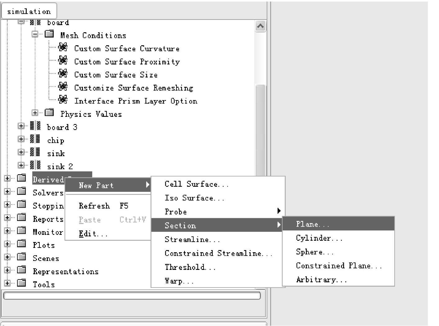
图3-96 设置截面
其中,origin指轴线所在方向或点位置,normal指轴线或点所在的法线方向。输入后的截面参数如图3-97所示。
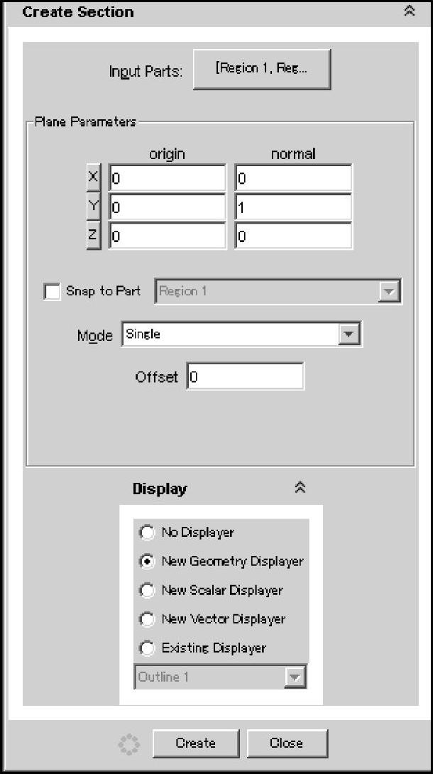
图3-97 Plane Parameters(平面参数)
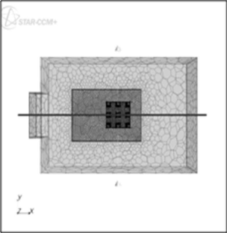
图3-98 截面在视图中的位置
确认新建截面的位置,在图3-98中显示为一条黑色直线。点击“Create”按钮,生成如图3-98所示的截面。
如图3-99所示,右键点击[Scenes]>[Mesh Scene 1]>[Displayers]>[Mesh 1],选择[Toggle Visibility],视图区的体网格消失。(www.chuimin.cn)
选择[Scenes]>[Mesh Scene 1]>[Displayers]>[Mesh 1]>[Parts]>[plane section],选择建立的平面截面,如图3-100所示。
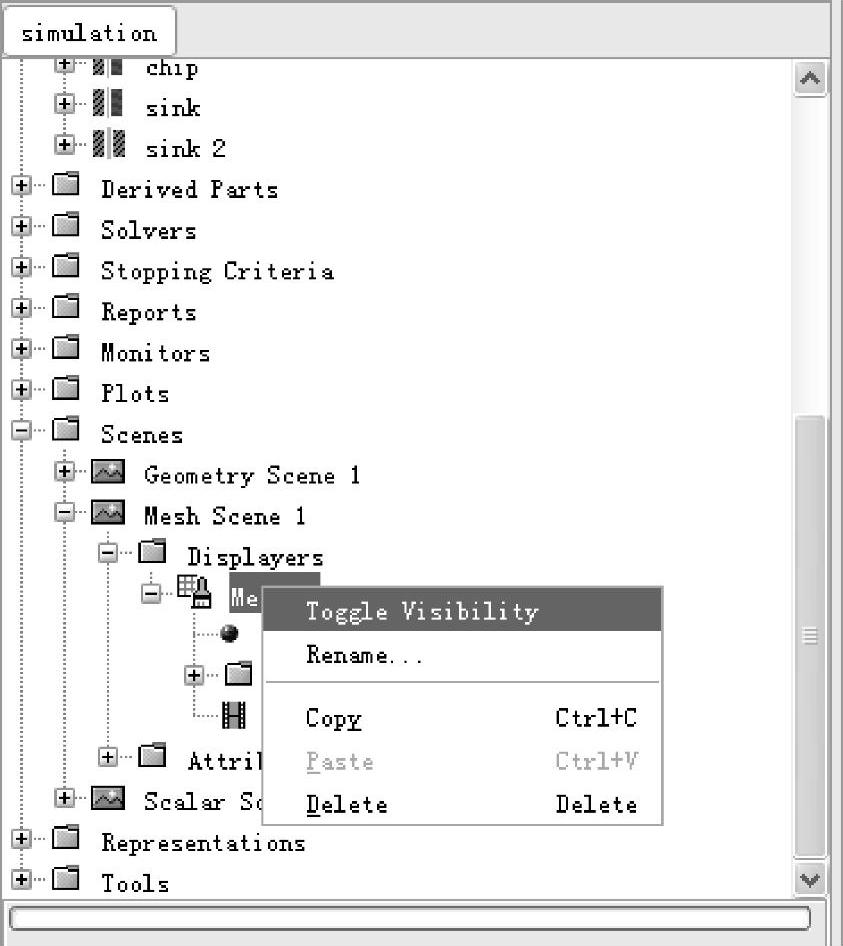
图3-99 选择Toggle Visibility
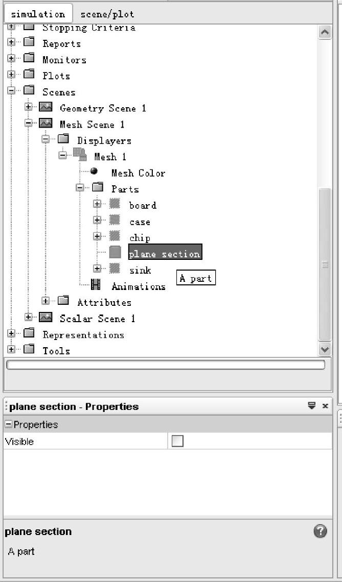
图3-100 选择plane section
选中plane section属性栏中的“Visible”项,如图3-101所示。
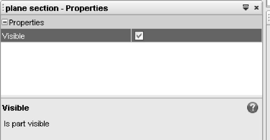
图3-101 显示网格
截面上的网格显示在视图窗口中,如图3-102所示。
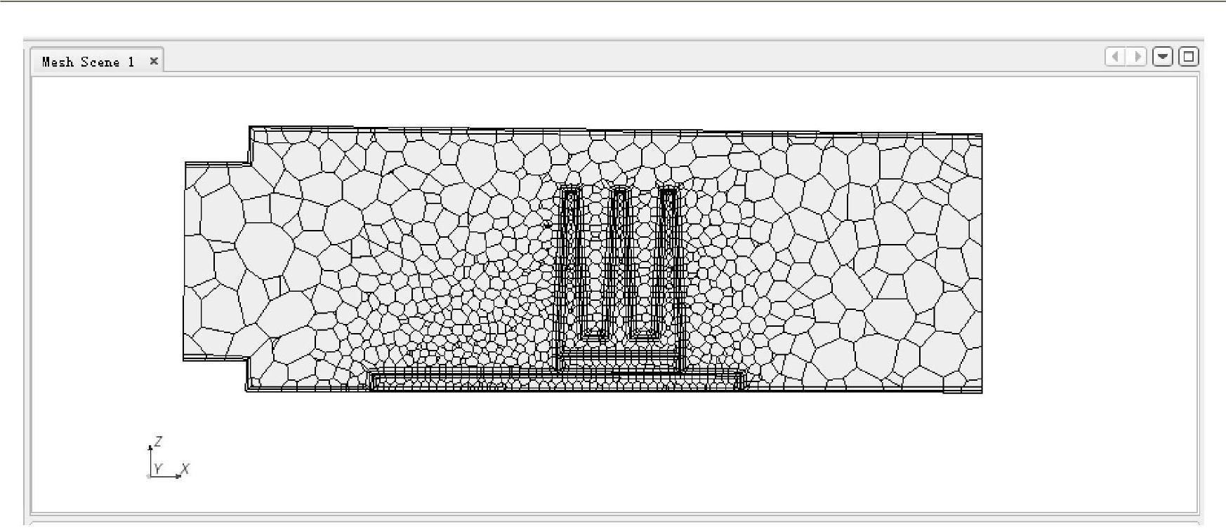
图3-102 截面上的网格


相关推荐