同时,小汽车前端地面设置滑移边界条件;小汽车附近及后部地面设置无滑移边界条件和移动壁面边界条件,以模拟地面与气流的摩擦作用。地面采用移动壁面边界条件,以消除假设条件为来流吹袭、列车静止而引起地面附面层对列车气动性能计算的影响。......
2023-10-17
1.设置进口、出口条件
选择[Regions]>[case]>[Boundaries]>[casein]>[Physics Conditions]>[Turbulence Specification],将其属性栏中“Method”项选择为“Intensity+Length Scale”方式,即湍流强度加涡的尺度的方式,如图3-55所示。
可以看到树形菜单[Regions]>[case]>[Boundaries]>[casein]>[Physics Values]中出现“Turbulence Intensity”和“Turbulence Length Scale”两项,如图3-56所示。
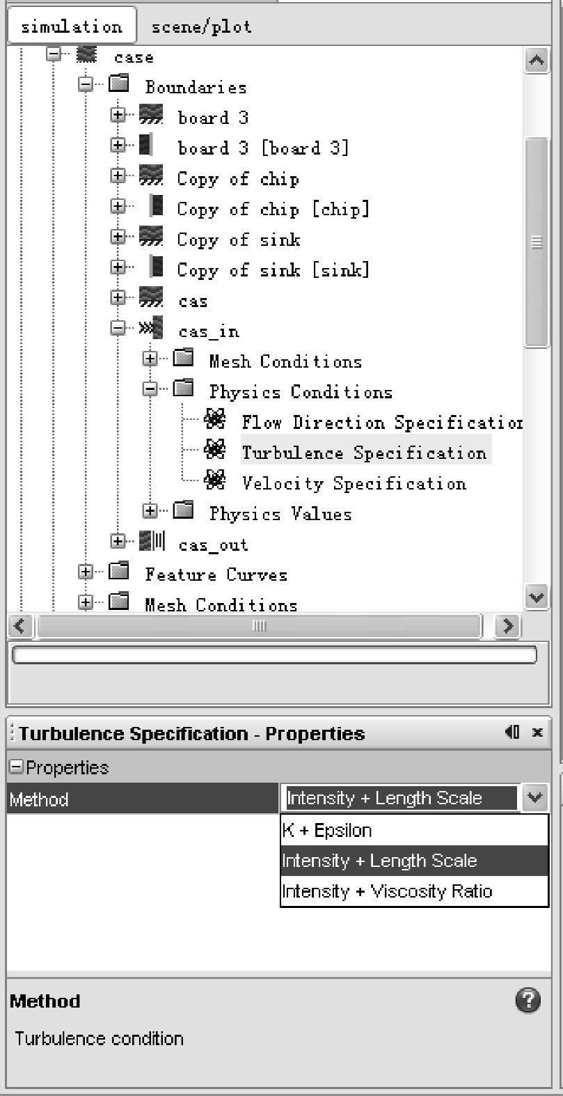
图3-55 湍流设置

图3-56 湍流条件设置
点击[Regions]>[case]>[Boundaries]>[casein]>[Physics Values]>[Turbulence In-tensity]>[Constant]。在其属性栏“Value”项中输入0.03,如图3-57所示。
点击[Regions]>[case]>[Boundaries]>[casein]>[Physics Values]>[Turbulence Length Scale]>[Constant]。在其属性栏“Value”项中输入0.0030,如图3-58所示。
湍流强度和涡的尺度的设置方法如下。
湍流强度:0.03~0.1
涡的尺度:
矩形边界条件:4×边界条件面积/边界条件周长×0.1
圆形边界条件:直径×0.1

图3-57 Turbulence Intensity选项
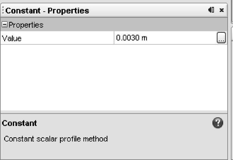
图3-58 Turbulence Length Scale选项
该模型的进口边界条件为速度随时间变化的条件关系式。
从计算开始到1200s的速度为0m/s,随后的速度为0.1m/s,如图3-59所示。

图3-59 进口速度条件
在Field Function中实现从0到1200s速度为0,随后速度为0.1m/s的表达式如下:
( Time<1200)?0∶0.1
注:具体的语法请参照Appendix。
Field Function是STAR-CCM+自带的功能,除了可以用来定义边界条件,也可以定义初始条件、物性值、后处理结果等。
生成速度随时间变化的函数的Field Function。右键点击[Tools]>[Field Function],选择[New],如图3-60所示。
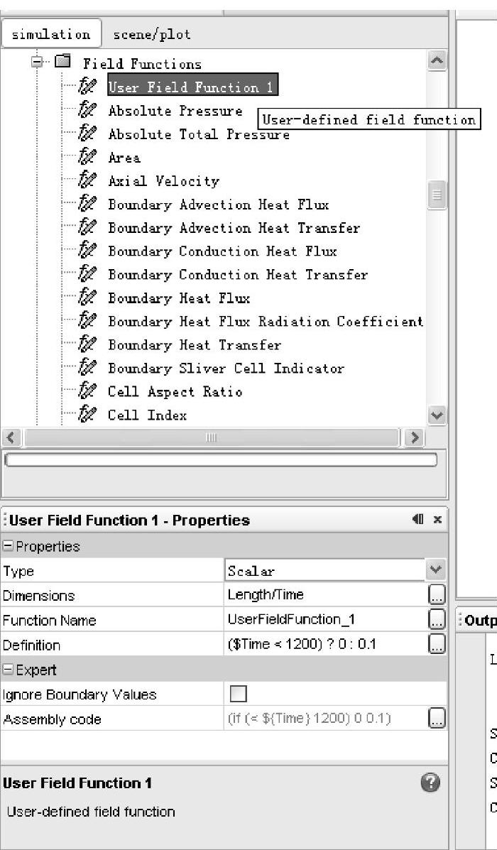
点击新生成的[User Field Function 1],如图3-61所示。在Definition项中,输入表达式“( Time<1200)?0∶0.1”。
点击[Dimensions]的 按钮。如图3-62所示,在“Length”项中输入1,在“Time”项中输入“-1”。因为是速度变量所以量纲为[Length/Time]。
在[Tools]>[Field Function]>[User Field Function 1]属性栏的“Definition”项中输入“( Time<1200)?0∶0.1”。
用做好的Field Function设置入口边界条件。如图3-63所示,选择[Regions]>[case]>[Boundaries]>[casein]>[Physics Values]>[Velocity Magnitude]。如图3-64所示,把属性栏中的“Method”项变更为“Field Function”。选择“Velocity Magnitude”属性栏“Meth-od”项中的“Field Function”,如图3-65所示,在随后出现的“Scalar Function”项中选择“User Field Function 1”。

图3-60 新建Field Functions
 (www.chuimin.cn)
图3-61 生成User Field Function 1
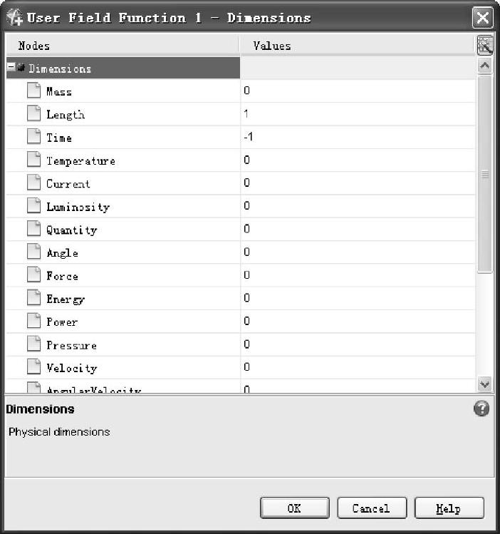
图3-62 User Field Function 1对话框
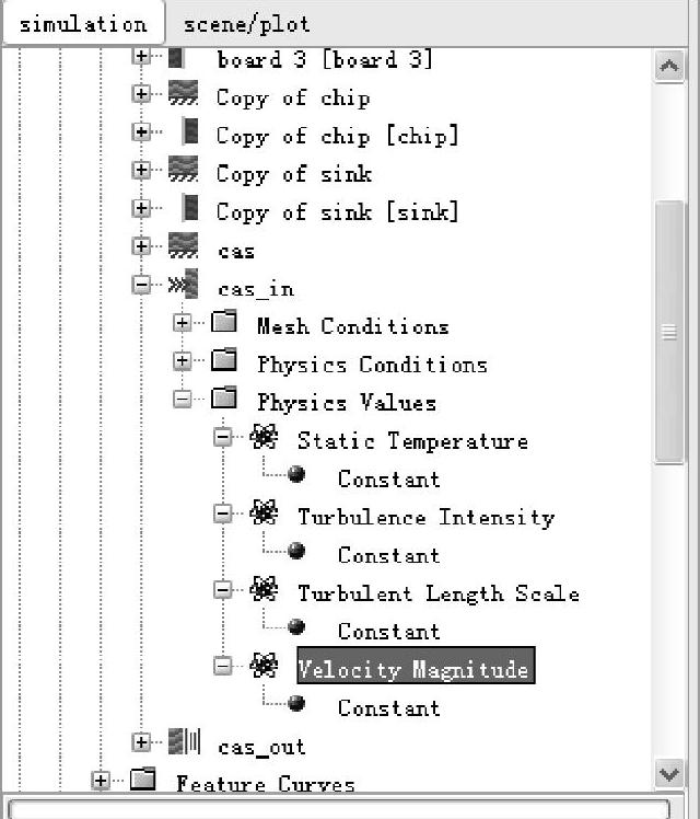
图3-63 Velocity Magnitude选项
设定Pressure Outlet的压力边界条件:
点击[Regions]>[case]>[Boundaries]>[caseout]>[Physics Values]>[Static Pres-sure]>[Constant]。确认属性栏中的“Value”项为[0.0 Pa],如图3-66所示。
点击[Regions]>[case]>[Boundaries]>[caseout]>[Physics Conditions],将“turbu-lence specification”等项采用与casein相同的设置。

图3-64 Method:Field Function选项
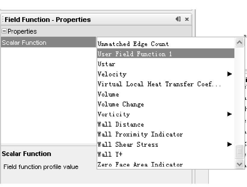
图3-65 Field Function:User Field Function 1选项
2.固体热源条件设定
固体热源条件设定应考虑IC芯片的发热条件。STAR-CCM+使用的发热量为单位体积的发热量,所以要对应转换单位。
点击[Regions]>[chip]>[Physics Conditions]>[Energy Source Option],设置能量选项,如图3-67所示。
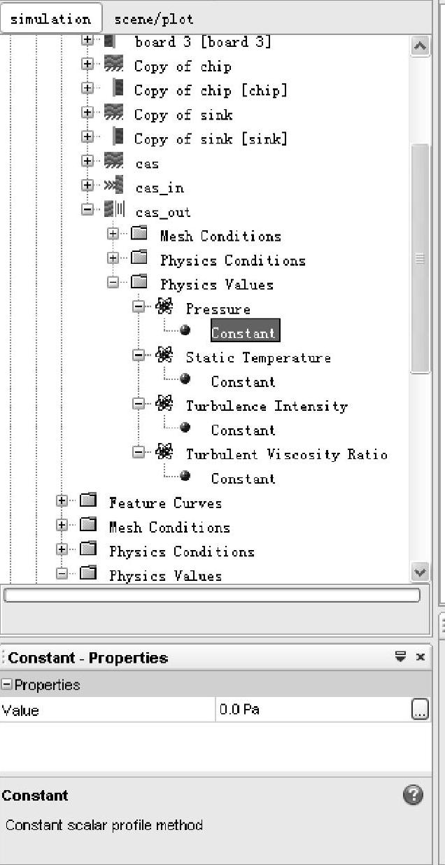
图3-66 Pressure值设定
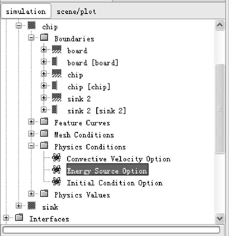
图3-67 Energy Source Option选项
选中属性栏中的“Energy Source Term”项,如图3-68所示。
点击图3-67中的[Regions]>[chip]>[Physics Values]>[Energy Source]>[Constant]。
chip的体积为1200×10-9m3,发热量为1.0W,转换为单位体积的发热量为833333.3W/m3。因此把属性栏中的Value更改为[8.33E5],如图3-69所示。
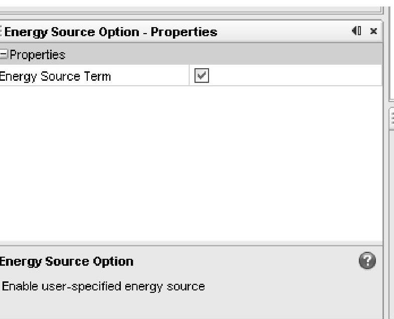
图3-68 选中Energy Source Term
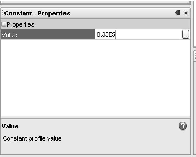
图3-69 单位体积的发热量
计算还需定义IC芯片和散热器间的热阻抗。点击[Regions]>[sink]>[Boundaries]>[Copy of sink 2],确定考虑热阻抗边界条件的位置。确认名为“Copy of sink 2[sink 2]”的Interface被定义了,如图3-70所示。
点击[Interfaces]>[sink 2]>[Contact Resistance]>[Constant]。面积为0.0004m2,热阻抗为0.5K/W,输入的单位面积热阻为0.0002m2·K/W。把属性栏中的Value值更改为[2E-4],如图3-71所示。

图3-70 热阻抗边界
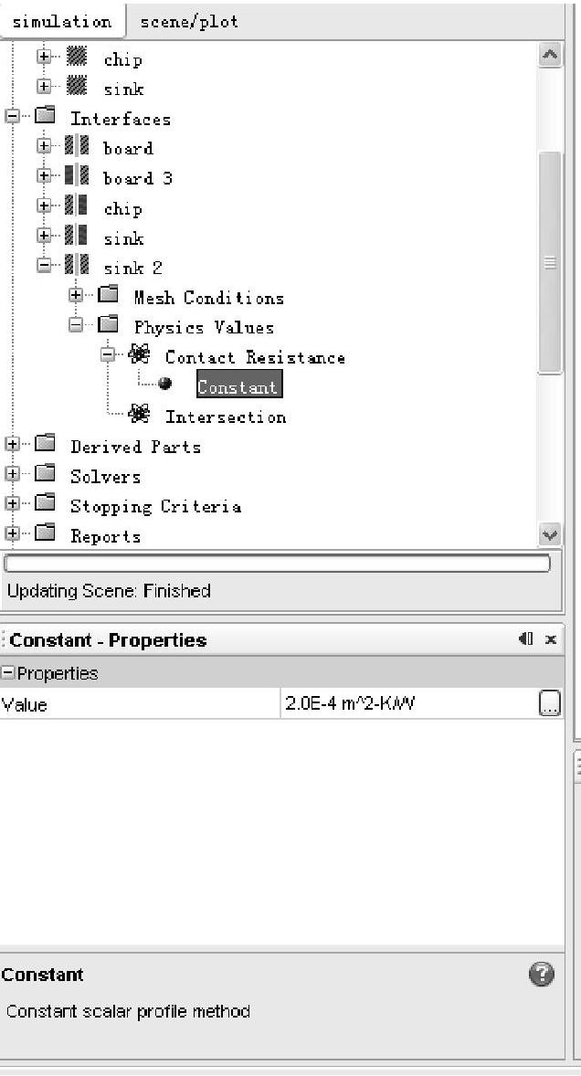
图3-71 Contact Resistance选项
有关STAR-CCM+与流场计算的文章

同时,小汽车前端地面设置滑移边界条件;小汽车附近及后部地面设置无滑移边界条件和移动壁面边界条件,以模拟地面与气流的摩擦作用。地面采用移动壁面边界条件,以消除假设条件为来流吹袭、列车静止而引起地面附面层对列车气动性能计算的影响。......
2023-10-17

故在明线无侧风运行工况计算边界条件设置的基础上,将两个侧面分别设置为速度进口、压力出口即可。列车表面、计算域顶面、地面边界条件保持不变。......
2023-10-17

图5-87 入口边界条件设定图5-88 输入入口速度3.出口边界条件图5-89 出口边界条件设定图5-90 出口压力条件设置为0出口处采用速度压力出口边界条件,如图5-89所示。图5-92 地面无滑移边界条件设定图5-93 移动壁面边界条件设定6.计算域侧面和顶面边界条件计算域两个侧面和顶面采用滑移边界条件。因为这三个面是虚拟的计算域表面,与壁面边界条件不同,故不用计及摩擦力。......
2023-10-17

计算流固耦合换热时固体的松弛因子默认取比较大的值,这样可以加速计算。图3-82 更改Logical Rule图3-83 设置Minimum Value5.更改计算结束条件点击[Stopping Criteria]>[Maximum Inner Iterations],如图3-84所示。如果计算过程中,输出窗口出现图3-86所示的不收敛信息,请加大“Inner Iterations”项的值,再继续进行计算。......
2023-10-17

如图5-119所示,点击[File]>[Auto Save],弹出如图5-120所示的“Auto Save”对话框。图5-116 新建压力检测点图5-117 监测点属性设定图5-118 选择Pressure图5-119 自动保存菜单项在“Auto Save”对话框中,选择[Trigger Type]>[Iteration],即按迭代次数的方式保存。其他项保持默认设置。图5-120 “Auto Save”对话框图5-121 计算步数设定图5-122 调整酷朗数3.Solvers设定一般情况下,可压缩流动采用Coupled Flow计算方法,而不可压缩流动采用Segregated Flow。......
2023-10-17

在边界层内,空气流速沿物体表面法向由零迅速增大到与来流速度基本一致。边界层的厚度在驻点处为零,然后逐渐向下游增加。为捕捉边界层内的气流流动特征,需要在物体表面划分较为细致的网格。Wall Thickness采用Number of Prism Layers、Prism Layer Thickness两项的设置方式。图2-92 边界层的三种划分方式图2-93 Number of Prism Layers图2-94 边界层厚度的两种设置方式边界层的厚度设置有设置占base size的百分比和设置厚度绝对值两种方式,如图2-94所示。......
2023-10-17

图3-44 确认操作复选“chip 3”、“chip 4”、“chip 5”和“chip 6”四边界,右键点击选择“Combine”合并,如图3-48所示。将“board”、“case”、“chip”和“sink”这四个边界设置为“wall”边界条件。图3-45 入口设定图3-46 出口设定图3-47 合并case边界图3-48 合并chip边界Boundary合并并进行重命名后的树形菜单如图3-49所示。Boundary合并准备完成,开始分割Region。......
2023-10-17

在“开始”选项卡中选择“条件格式”→“数据条”选项,选择渐变填充样式下的“浅蓝色数据条”样式,如图11-43所示。图11-42选中区域图11-43设置条件格式条件格式效果如图11-44所示,可以注意到,负数对应的数据条是反方向的红色色条。图11-49条件格式规则管理器设置图标的显示条件,如图11-50所示。......
2023-08-18
相关推荐